
Toyota 2Z engine factory workshop and repair manual on PDF can be viewed using free PDF reader like adobe or foxit or nitro . File size 7 Mb searchable PDF document Chapters Index:GENERAL ENGINE TUNE-UP ENGINE OVERHAUL FUEL SYSTEM SST LIST COOLING SYSTEM LUBRICATION SYSTEM STARTING SYSTEM CHARGING SYSTEM SERVICE STANDARDS About the 2Z engine Engine type 2Z Number of cylinders mounting Inline 4 vertically mounted. Bore x stroke 98 times;115mm Total piston displacement 3469cc Valve mechanism OHV Combustion chamber type Direct injection type Cycle Cooling system 4 cycle water cooled Performance Maximum Output 42kW (@2200rpm) Maximum Torque 200Nm (@1600rpm) Dimensions (length x width x height) 722 times;535 times;753mmDry weight 212kgToyota 2Z engine factory workshop and repair manual Download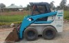
Toyota Skid Steer 4SDK3 4SDK4 4SDK5 4SDK6 4SDK8 4SDK10 factory workshop and repair manual on PDF can be viewed using free PDF reader like adobe or foxit or nitro .File size is 7 Mb searchable PDF. General Engine (only covers engine removal and adjustment not engine repair) HST Reduction Gear Steering Axle Brake Body Steering Body Lift Arm and Bucket Bracket Cylinders Oil Pump Oil control valve Hydraulic systems AppendixWiring diagramToyota Skid Steer 4SDK3 4SDK4 4SDK5 4SDK6 4SDK8 4SDK10 factory workshop and repair manual
Toyota 1DZ-II engine factory workshop and repair manual on PDF can be viewed using free PDF reader like adobe or foxit or nitro . File size 7 Mb searchable PDF document Chapters Index:GENERAL ENGINE TUNE-UP ENGINE OVERHAUL FUEL SYSTEM PCV SYSTEM COOLING SYSTEM LUBRICATION SYSTEM STARTING SYSTEM CHARGING SYSTEM APPENDIX About the 1DZ-II engine Engine type 1DZ Number of cylinders mounting Inline 4 vertically mounted. Bore x stroke 86 times;107mm Total piston displacement 2486cc Valve mechanism OHV Combustion chamber type Swirl chamber type Cycle Cooling system 4 cycle water cooled Performance Maximum Output 39kW (@2400rpm)Maximum Torque 160Nm (@2300rpm)Toyota1DZ-II engine factory workshop and repair manual Download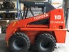
Toyota Skid Steer Loader SDK10 factory workshop and repair manual on PDF can be viewed using free PDF reader like adobe or foxit or nitro .File size is 12 Mb 236 pages searchable PDF. General Engine Hydrostatic Transmission Final Reduction Gear Steering Axle Brakes Body Frame Lift Arms and Bucket Bracket Cylinders Oil Pump Oil Control Valve Hydraulic SystemAppendixToyotaSkid Steer Loader SDK10 factory workshop and repair manual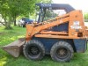
Toyota Skid Steer Loader SGK6 SDK6 SDK8 factory workshop and repair manual on PDF can be viewed using free PDF reader like adobe or foxit or nitro .File size is 13 Mb 300 pages searchable PDF. General Engine Hydrostatic Transmission Final Reduction Gear Brakes Body Frame Lift Arms and Bucket Bracket Cylinders Oil Pump Oil Control Valve Hydraulic System AppendixToyotaSkid Steer Loader SGK6 SDK6 SDK8 factory workshop and repair manual
Toyota 2Z engine factory workshop and repair manual download
Toyota Skid Steer 4SDK3 4SDK4 4SDK5 4SDK6 4SDK8 4SDK10 factory workshop and repair manual
Toyota 1DZ-II engine factory workshop and repair manual download
Toyota Skid Steer Loader SDK10 Factory Workshop Manual download
Toyota Skid Steer Loader SGK6 SDK6 SDK8 Factory Workshop Manual download
A skid loader, skid-steer loader or skidsteer is a small, rigid-frame, engine-powered machine with lift arms used to attach a wide variety of labor-saving tools or attachments. Skid-steer loaders are typically four-wheel vehicles with the wheels mechanically locked in synchronization on each side, and where the left-side drive wheels can be driven independently of the right-side drive wheels. The wheels typically have no separate steering mechanism and hold a fixed straight alignment on the body of the machine. Turning is accomplished by differential steering, in which the left and right wheel pairs are operated at different speeds, and the machine turns by skidding or dragging its fixed-orientation wheels across the ground. The extremely rigid frame and strong wheel bearings prevent the torsional forces caused by this dragging motion from damaging the machine. As with tracked vehicles, the high ground friction produced by skid steers can rip up soft or fragile road surfaces. They can be converted to low ground friction by using specially designed wheels such as the Mecanum wheel. Skid-steer loaders are capable of zero-radius, "pirouette" turning, which makes them extremely maneuverable and valuable for applications that require a compact, agile loader. Skid-steer loaders are sometimes equipped with tracks instead of the wheels, and such a vehicle is known as a multi-terrain loader. Unlike in a conventional front loader, the lift arms in these machines are alongside the driver with the pivot points behind the driver’s shoulders. Because of the operator’s proximity to moving booms, early skid loaders were not as safe as conventional front loaders, particularly during entry and exit of the operator. Modern skid loaders have fully enclosed cabs and other features to protect the operator. Like other front loaders, it can push material from one location to another, carry material in its bucket or load material into a truck or trailer. The first three-wheeled, front-end loader was invented by brothers Cyril and Louis Keller in Rothsay, Minnesota, in 1957.[2] The Kellers built the loader to help a farmer, Eddie Velo, mechanize the process of cleaning turkey manure from his barn. The light and compact machine, with its rear caster wheel, was able to turn around within its own length, while performing the same tasks as a conventional front-end loader.[2]
The Melroe brothers, of Melroe Manufacturing Company in Gwinner, North Dakota, purchased the rights to the Keller loader in 1958 and hired the Kellers to continue refining their invention. As a result of this partnership, the M-200 Melroe self-propelled loader was introduced at the end of 1958. It featured two independent front-drive wheels and a rear caster wheel, a 12.9 hp (9.6 kW) engine and a 750-pound (340 kg) lift capacity. Two years later they replaced the caster wheel with a rear axle and introduced the M-400, the first four-wheel, true skid-steer loader. The M-440 was powered by a 15.5 hp (11.6 kW) engine and had an 1,100-pound (500 kg) rated operating capacity. Skid-steer development continued into the mid-1960s with the M600 loader.
A skid-steer loader can sometimes be used in place of a large excavator by digging a hole from the inside. The skid loader first digs a ramp leading to the edge of the desired excavation. It then uses the ramp to carry material out of the hole. The skid loader reshapes the ramp making it steeper and longer as the excavation deepens. This method is particularly useful for digging under a structure where overhead clearance does not allow for the boom of a large excavator, such as digging a basement under an existing house. Several companies make backhoe attachments for skid-steers. These are more effective for digging in a small area than the method above and can work in the same environments. Other applications may consist of transporting raw material around a job site, or assisting in the rough grading process.
The original skid-steer loader arms were designed using a hinge at the rear of the machine to pivot the loader arm up into the air in an arc that swings up over the top of the operator. This design tends to limit the usable height to how long the loader arm is and the height of that pivot point. In the raised position the front of the loader arm moves towards the rear of the machine, requiring the operator to move extremely close to or press up against the side of a tall container or other transport vehicle to get the bucket close enough to dump accurately. At the highest arm positions the bucket may overflow the rear of the bucket and spill directly onto the top of the machine’s cab.
An extended reach design uses multiple hinges and parallel lifting bars on the loader arm, with the main pivot points towards the center or front of the machine. This allows the loader arm to have much greater operating height while retaining a compact design, and allows the vertical movement to be less of an arc and more straight-up vertical, to keep the bucket forward of the operator’s cab, allowing safe dumping into tall containers or vehicles.